Programming Examples
Arduino program to implement Two way traffic signal system.

Write a program Two - way traffic 🚦 signal and implement it using an Arduino uno board.
Creating a two-way traffic signal system using an Arduino Uno involves controlling multiple LEDs to simulate the traffic lights. We'll use red, yellow, and green LEDs for each direction and create a timing sequence to simulate a traffic light system.
Components Needed:
- Arduino Uno
- 2 Red LEDs
- 2 Yellow LEDs
- 2 Green LEDs
- 6 Resistors (220 ohms each)
- Breadboard
- Jumper wires
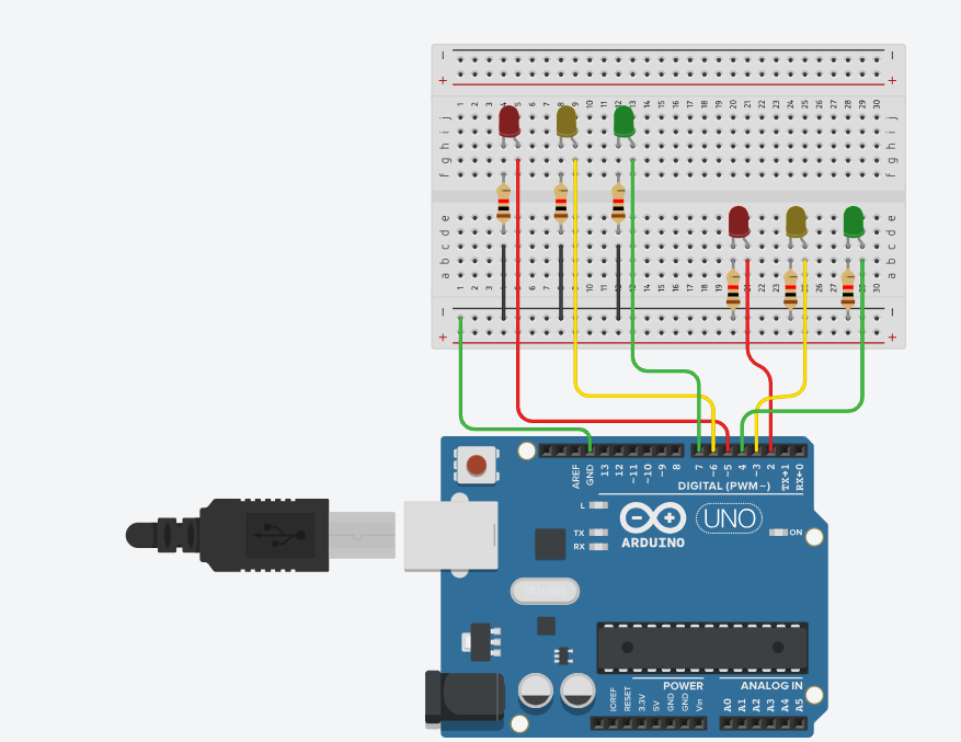
- Circuit Diagram:
LED Connections:
Direction 1:
- Connect the anode (positive) of the Red LED to digital pin 2 on the Arduino through a 220-ohm resistor.
- Connect the anode of the Yellow LED to digital pin 3 on the Arduino through a 220-ohm resistor.
- Connect the anode of the Green LED to digital pin 4 on the Arduino through a 220-ohm resistor.
Direction 2:
- Connect the anode of the Red LED to digital pin 5 on the Arduino through a 220-ohm resistor.
- Connect the anode of the Yellow LED to digital pin 6 on the Arduino through a 220-ohm resistor.
- Connect the anode of the Green LED to digital pin 7 on the Arduino through a 220-ohm resistor.
- Connect the cathodes (negative) of all LEDs to the GND pin of the Arduino.
Solutionconst int red1 = 2;
const int yellow1 = 3;
const int green1 = 4;
const int red2 = 5;
const int yellow2 = 6;
const int green2 = 7;
void setup() {
pinMode(red1, OUTPUT);
pinMode(yellow1, OUTPUT);
pinMode(green1, OUTPUT);
pinMode(red2, OUTPUT);
pinMode(yellow2, OUTPUT);
pinMode(green2, OUTPUT);
}
void loop() {
// Direction 1 Green, Direction 2 Red
digitalWrite(green1, HIGH);
digitalWrite(red2, HIGH);
delay(5000); // Green for 5 seconds
// Direction 1 Yellow, Direction 2 Red
digitalWrite(green1, LOW);
digitalWrite(yellow1, HIGH);
delay(2000); // Yellow for 2 seconds
// Direction 1 Red, Direction 2 Red
digitalWrite(yellow1, LOW);
digitalWrite(red1, HIGH);
delay(1000); // All red for 1 second
// Direction 1 Red, Direction 2 Green
digitalWrite(red2, LOW);
digitalWrite(green2, HIGH);
delay(5000); // Green for 5 seconds
// Direction 1 Red, Direction 2 Yellow
digitalWrite(green2, LOW);
digitalWrite(yellow2, HIGH);
delay(2000); // Yellow for 2 seconds
// Direction 1 Red, Direction 2 Red
digitalWrite(yellow2, LOW);
digitalWrite(red2, HIGH);
delay(1000); // All red for 1 second
// Direction 1 Red off, reset for next cycle
digitalWrite(red1, LOW);
digitalWrite(red2, LOW);
}
Output/ Explanation: Pin Definitions:
- Pins 2, 3, 4 are assigned to red, yellow, and green LEDs for Direction 1.
- Pins 5, 6, 7 are assigned to red, yellow, and green LEDs for Direction 2.
Setup:
- Set all LED pins as OUTPUT in the setup() function.
Loop:
- The main loop() function alternates between the states of the traffic lights for the two directions.
- Each direction gets a green light for 5 seconds, a yellow light for 2 seconds, and then both directions get a red light for 1 second.
- This sequence ensures that one direction has a green light while the other has a red light, followed by a brief period where both directions have a red light.
Steps to Implement:
- Assemble the circuit on the breadboard according to the diagram.
- Connect the Arduino to your computer.
- Open the Arduino IDE, copy and paste the code, and upload it to the Arduino Uno.
- Observe the LEDs as they cycle through the traffic light sequence.